Antenna Control System
Antenna Control System
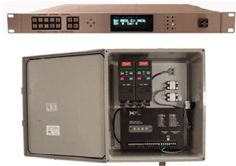
Model No. ATX 3000
ATX Features-
- Multiple Peaking and history track algorithm set - Multiple user selectable peaking/ history track algorithms. SSC has introduced our best peaking algorithm ever! With our newest peaking algorithm the ATX 3000 delivers maximum performance with minimal signal loss.
- Foul weather feature - FWx - Don’t let rain fade and controller performance ruin your link! Our latest foul weather feature allows a user to either locally or remotely select our new FWx - foul weather feature mode. When bad weather is approaching or has arrived, the user can select our new foul weather mode feature. With our new proprietary FWx mode the tracker delivers maximum performance and signal during bad weather. The user can select the duration of the FWx based on the weather conditions.
- Remote operation from anywhere in the world! – Satellite system introduces full remote control for your antenna controller. Now with our latest Monitor and Control software we have added full antenna control. Great for remote operation of multiple antennas or correct antenna position instantly without having to travel to the site whether it is 1 mile away or 10,000 miles away!
- AC and DC solutions- Multiple AC and DC solutions available, please contact factory for your application. Satellite Systems announces the new control GUI Version 2.0 for our antenna control product line. Enhanced control features allow for remote control of your antenna and additional monitoring tools are included such as strip charting for signal strength, Azimuth & Elevation movement. Version 2.0 also includes a new event-triggered alarm feature that allows for email notification to your laptop / cell phone or PDA. Alarms are triggered via signal strength, loss of signal, and other conditions. New logging to file feature allows for analysis of controller events. Easily imported to Excel. Revolving log file saving feature automatically closes the file and starts a new file once per day for archiving and date stamping purposes.
Positioning Methods-
- Designate:Automatically moves the antenna in each axis to one of 99 pre-stored satellite positions.
- Direct Az/El: Automatically moves the antenna in each axis to the coordinates entered via the front panel
- Jog: Manually moves the antenna in each axis in response to front panel controls.
- Peak:Performs a peaking algorithm on the current target.
- Step Track:Automatically performs peaking algorithm in response to input signal level decreasing below a programmable minimum
- History Track:Automatically moves the antenna in each axis along a sidereal time tagged path. (History track is often referred to as Memory Track or Program Track)
- External: Moves the antenna in each axis in response to commands received through the active monitor and control port
Performance
- Accuracy:Antenna pointing accuracy within ten percent of the 3dB Beamwidth. Tracking Resolution: > 0.05 degrees with Properly specified position Sensor.
Interfaces-
- Reference:Accepts input of linear, analog signal reference from 0 - 20 VDC. Internal op amp circuit provides pre-scaling of gain and slope of tracking reference signal. Final scaling is provided through software
- M&C: Accepts RS-232 / RS-485 (4-wire) data / Ethernet via RJ 45 10/100 Base T for remote monitor and control of all controller functions. ATX monitor / control software suite is included
- Front Panel:Large Graphic VFD displays antenna position, signal level and operating mode. Keypad provided for user inputs.
- Motor Control: The rack mounted microprocessor controller is linked to any of motor control options by serial interface cable.
- Prime Power (ACU):90 - 260 VAC, 47 - 63 Hz, single-phase, auto sensing, 65 watts maximum.
Monitor and Control Software for ATX 3000 Antenna Controller-
- Event triggered alarms:- Any alarm conditions can be sent to the user via email to your laptop /cell phone or PDA. Events can be triggered via signal strength, AZ, EL, & POL movements, communication errors and other threshold parameters.
- Antenna position and parameter control feature set
- Large easy to read signal strength panel.
- Event triggered alarms / Easy to use email control. Email multiple users / multiple alarm parameters.
- Status monitor- The status monitor panel allows for real time data of your systems status.
- Strip Chart utility– Strip charting utility allows for recording of signal strength and AZ&EL motor movements. Events are recorded and presented on time based event chart. Additional logging feature allows for tab delimited file that can be imported into your favorite spreadsheet program. The log files can be automatically saved and restarted on a daily basis and pulled up later for review of tracking performance.
- Revolving log file saving feature allows user to automatically back up log files for later analysis of controller events. Easily imported to Excel or other spread sheet programs.
Antenna Drive Units for AC Motors-
- Solid-state variable frequency 3 phases AC motor controllers with microprocessor motor speed management.
- Static braking with torque at 150% of rated motor torque.
- Variable speed control 0 to 60 Hz with constant torque.
- Low frequency voltage boost 150% starting torque under 20% speed.
- Local jog control and Emergency Stop switch are provided at the ADU.
- Optional handheld remote jog control is available. HP configuration options: 1 - 10 hp available.
AC System Standard Dimensions-
ACU: 1 RU, 19" x 15.5" x 1.75"
ADU: Dual axis 3 phase AC motor control unit is a NEMA-4 outdoor enclosure 16"W x 20"H x 9"D. Some configurations may require a larger enclosure.
Interconnections-
Local AC main power is required at the ADU.
A two conductor, 20 gauge shielded cable from the ADU to indoor ACU interface is required.
Required Limit switches connect to ADU.
Extra Emergency stop switches may connect to ADU.
High resolution absolute, brushless resolvers or optical position encoders mount directly on antenna Az and El pivot axis.
Antenna Drive Units for DC Motors-
DC Motor jacks provided by SSC in 12 - 48 inch stroke lengths. Built in encoder feedback. 24 / 36 VDC / integrated limit switches. (DC systems jacks are quoted separately).
DC System Standard Dimensions-
ACU: 1 RU, 19" x 15.5" x 1.75"
ADU:1 RU, 19" x 15.5" x 1.75" (Enclosure solution also available).
Options-
Motors, Gear reducers, Jack screws, Limit switches, Emergency stop switches, umbilical control.