Beacon Tracking Receiver
Beacon Tracking Receiver
Model No. 1) BR23-L 2) /3430L
A Beacon Tracking Receiver for antenna step tracking and automatic uplink power control.
- Wide bandwidth, 930 to 2300 MHz standard
- Digital level reference setting, -40 to -100 dBm on 0.5 dB steps
- Rs-232/422/485 and Standard
The output of the Beacon Receiver is a DC voltage proportional to the input signal level to facilitate both antenna tracking control and automatic power control. A Loss of Carrier indicator is provided in the event the tracking signal is lost. Form "C" relay contacts provide an external Loss of Carrier Alarm. A front panel VFD displays operating frequency, relative signal level, carrier lock or alarm, and input level.
| Specifications | |
| Input Frequency | 930 - 2300 MHz |
| Input Level | -40 to -100 dBm typical |
| Level Adjust | 9Digital, 0.5 dB steps |
| Level Accuracy | ±0.4 dB per step ±4 dB over entire range |
| Tracking Slope | 0.5 V/dB |
| Tracking Linearity | ±0.25 dB |
| Frequency Selection | 10 kHz steps |
| Min. input level for Lock | -110 dBm |
| Input Connector | Type “N” Female, 50 ohm* |
| Threshold | 4 dB C/N for acquisition < 1 dB C/N for carrier lock |
| Tracking Response | 0 to +10 VDC over 20 dB input range standard other ranges optional**** |
| Alarms | Form-C relay contacts |
| AFC | ±25 kHz** |
| Noise Bandwidth | 50 kHz |
| M&C | RS-232 or RS-422/485 Continuous Data Streaming option/ streaming signal strength output via a dedicated RS-232 DB 9 connector |
| M&C Connector | DB-9 Female |
| Mechanical | |
| Output Connector | Modular socket & plug |
| Dimensions | 1 RU, 19" x 16" x 1.75" |
| Power | |
| Prime Input Power | 90-260 VAC, 47-63 Hz, auto-sensing, 45 Watts max |
| LNB Power | +24 Volts @ 1 Amp available on center conductor Selectable In/Out*** |
Filtering
O Standard AFC and Standard 0.4 Hz output smoothing filter
A No AFC – Use for tracking Wide Data Carriers. Standard 0.4 Hz output smoothing filter
S No AFC and No 0.4 Hz output smoothing filter.
T No 0.4 Hz output smoothing filter. Standard AFC
Bandwidth
O 50 kHz pre-detection bandwidth
5 No 0.4 Hz output smoothing filter. Standard AFC
Input Connector on Rear of BTR
N 50 ohm N female connector
B 50 ohm BNC female connector
Q 50 ohm TNC female connector
S 50 ohm SMA female connector
M&C
RS-232
RS-422/485
Optional Continuous Data Streaming
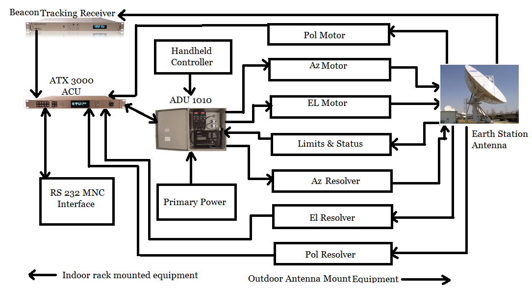
Antenna System Configuration Block Diagram